|
How to
open up your faulty Logik IR100 Internet Radio to replace the rotary encoder

Before we start it must
be emphasised that all electronic devices are fragile and more so when they
are opened. In particular you must ensure that the radio is unplugged from
the mains (doh!) before you start. Inside the radio is a power supply board
on this are several capacitors. These are really batteries that hold a
charge (of several AMPS) for hours if not days. Many people do not believe
this but whilst a shock from a charged capacitor will not be deadly the
flash and loud crack when you accidentally short it out can easily cause
your screwdriver to slip resulting in serious damage to the radio – or you
if you stick it into your thumb! Fortunately you will not be dealing with
power supply faults (nor should you if you are inexperienced) so you can
heed this advice and move on.
WE DO NOT READ, NOR DO WE EVER FOLLOW INSTRUCTIONS
SUCH AS THESE. AFTER ALL WE “KNOW IT ALL”! IF YOU CHOSE TO GO AHEAD WITHOUT
HEEDING THESE WARNING THEN WHO ARE WE TO COMPLAIN – BUT DON’T SAY WE DIDN’T
WARN YOU!
The Logik IR100 Internet
Radio is made to a modular design with five or six different boards screwed
together with interconnections using ribbon cables that are plugged in. One
end of each ribbon cable is soldered into its circuit board and the other
has a plug which fits into a corresponding socket on another board. Once you
have the radio open the
first thing to do is look carefully where each plug goes – they can look
similar if you have not taken a careful look before starting. One idea is to
write on each cable with a unique mark try using a pencil or a felt tip.
There is also a loudspeaker plug which connects to the main power board.
This especially MUST be reconnected before reconnecting the mains or you may
blow the 8Watt amplifier.
It will immediately become
apparent that the construction of this radio is cheap – very cheap! For
example the end of each wire that is soldered into the board should use a
special connector which stops strain on the wire when you pull the plug on
the other end. On the Logik they have chosen to simply use some glue to
“reinforce” the soldered end! Pull too hard, or even flex the wire too much
and there is the real chance that you will break a wire inside the plastic
covering at the soldered end, so be gentle.
Experienced radio and
television engineers are well used to know how much they can pull a wire
without it breaking, if this is your first attempt at a repair then use the
rule of pulling just as little as you can and BE CAREFUL! IF you break a
wire then on no account reconnect the mains supply “to see if it still
works” as you run the real risk of damaging your radio. Mend the break
first! The micro controller board (which looks different to the others as it
is a different colour and well made) is really a small computer so break
that and expect a large bill to get it fixed – probably more than the radio
is worth!
Right, all the warnings out
of the way and if we haven’t put you off you can go ahead with the
instructions (or actually really suggestions) as to how you can get at the
encoder board to replace the rotary control.
The first job is to remove
the large knob on the front that is attached to the encoder that you are
later going to remove and then solder its replacement in to place. Some
people like to quite literally get the knob out of the way first; others
like to leave it until later. Either way this has to come off some time and
its removal is probably the hardest part of the whole repair. If yours does
not come away with a sharp tug or two perhaps wait a bit until later when we
will make some suggestions how to make the job easier.
As you will guess the
encoder is right at the front of the radio so as you go in from the back
there is a fair amount of stuff to move to get at it! First remove the six
screws holding the back on using a medium size cross head screwdriver that
is at least 15 cm long. Most screws will come straight out but at least one,
and probably more will get stuck in their mounting however much you turn
them. This doesn’t really matter and can be sorted out later. One suggestion
is to get a small pot to put all the screws in, you will probably end up
with up to 20 screws of different sizes before you start to reassemble so it
might be as well to mark them to make sure that you put the right screw back
into the right socket.
To help removing the back
you can put two fingers into the acoustic dome on the back to get some
purchase – do NOT pull on the mains lead, however much you want to, as it is
not well held - inside some sets it’s just glued in place! Don’t pull too
hard on the back either as there are three wires connected between the
modules fixed to the back cover and the rest of the set – pull these too
hard and you’ll break the wires! Also beware that some people have bought
“faulty” radios on eBay and found a collection of parts inside that are not
even plugged together – this has happened at least twice to our knowledge!
If you find any of the plugs out of their sockets then be very suspicious of
proceeding as if they are that deceitful the seller will obviously blame you
for the radio not working!
If you do decide to
continue then make sure that you have a full set of boards and not two the
same somewhere! The Barracuda computer boards are getting harder to find and
there will be a temptation to sell a non-working radio with this missing.
Right back to your “honest”
radio. Having pulled the back perhaps an inch or so away carefully look
inside the radio and you will see two ribbon cables and one loudspeaker
cable stopping your pulling any further. Before proceeding follow our
earlier recommendation to look carefully at which plug goes into which
socket and write it down somewhere. Two of the cables plug into sockets
on boards attached to the back, and one cable has its plug end inside the
set. All we can suggest is that you carefully try to separate these plugs
starting with the two on the back of the radio. There is some “nail varnish”
type stuff which is meant to hold the plugs together – it doesn’t – but it
does help show you which way round to reassemble the cables later. To
separate try putting your nail under the plastic lip of each plug and socket
combination but try not to pull on the cable itself. Do make sure you’re
careful or you’ll not have a working radio after all your trouble! Once you
have the three connectors separate you are now able to move the back away
from the set.
Next look underneath the
set at the front and you will see a single screw – this is the only
countersunk screw in the radio so don’t lose it as you can’t swap it with
anything else when you put it back together. Remove this screw and you may
see a red spacer underneath, if so pull that out and store both safely in
your pot.
The front of the set will
now come away quite easily (the glue holding it will have dried up) and you
will be left with the empty wooden case in one hand and the front panel in
the other. If you decided to leave levering off the large knob earlier then
you can put it off no longer, so put something onto the plastic to reinforce
and act as a fulcrum as well as saving too much damage to the plastic, then
with your flat bladed screwdriver lever the large knob off. You are aiming
for the screwdriver to engage with the centre of the knob, not the edge
which is very thin and will crack with too much pressure. The knob WILL
come, but may take a lot of persuasion and some ingenuity to remove. Just
keep trying, it’s only plastic! Perhaps try putting something slim and
strong to lever against? Sometimes these knobs just drop off (quite
literally) as they are only held with a bit of double sided tape, others are
held like they have been held on with epoxy resin. There is unfortunately no
way out of it, if you want to replace the encoder then to get inside the
knob MUST come off - by fair means or foul! Next pull off the volume knob
(usually much easier) and you can start to breathe again.
Put the front face down on
something to save it getting scratched (a pillow or some foam perhaps?) and
start disassembly. Fortunately you do not need to remove all the screws that
you can see! There are six to take the bracket that holds the display and
other boards off, two are located at the very bottom where they screw
through the grey plastic, one is on the edge beside the “dogleg”, and
another three at the top. Yes three! In the very corner at the edge is what
looks like an ordinary screw but it is about 4 times the length of all the
others so keep twiddling! There is one other normal length screw in the
other corner and then one more that is hidden under the cable at the top.
You don’t need to unplug this cable (at all) just push it gently over and
remove the screw. The whole module will now come away in your hand.
Turn it over and you will
see the boards with the buttons, controls, and the display – be very careful
and do not be tempted to clean the display as it is not made of normal
plastic. It is quite soft and marks easily and permanently, leave it well
alone! If you MUST remove a bad mark try alcohol and don’t rub too hard.
All you need do now is
remove the four short screws that hold the control board in place. You will
see two ribbon cables coming from the control board. One goes through the
slot and leads right to the back of the set – you must replace the wire
through the slot, and the other just goes under the wire leading to the
micro control board. This plug needs removing – gently – and make sure than
when you come to reassemble you put the wire back under the other. If you
don’t keep the cable dressing the same there is a chance that one will get
snagged by the case when you come to reassembly. I have done this and broke
the cable.
So after two pages of notes
you finally have the board that you need in your hand – time to warm up your
soldering iron!
There are (at least) two
different styles of control board – one original and one modified. Look at
the photos to see if your board is the modified variety as some people have
found that their replacement encoder works better when the modification is
removed. It’s up to you but you might choose to check both ways.
If you do want the
modification removed then you will need to take away two resistors
(cylindrical components with colour code) and then BRIDGE where they were
with pieces of wire. You are replacing the resistors with wire NOT joining
where the components were together – hope that’s 100% clear! Also remove the
extra capacitor (small brown flat round component) that is next to them.
There is a further component in the mod which is a capacitor near where the
wire leaves the board. This can stay as it’s difficult to remove but if you
wish to by all means do have a go at removing it, entirely at YOUR risk!
Next you need to “simply”
unsolder the old rotary encoder using a solder sucker or desoldering braid.
Clean the position and replace with the new encoder. Do be aware that the
circuit board is of rubbish quality and it is extremely easy to break one or
more of the tracks (often invisibly) when you apply heat so get your test
meter out and check now, then check again! We have broken tracks even after
knowing all this and the breaks are often at the edge of the etching where
the modifications have been soldered over. That’s a break underneath the
soldering which is not connected - really, really nasty!
If your original encoder
did work after a fashion then it might be an idea to desolder it carefully
and put is aside safely so if something goes wrong you at least have
something to replace to test and see where the problem lies. You could even
try opening up the encoder by bending the clips, clean the four contacts
with some alcohol, clean the track and reassemble. Until we obtained the
replacement encoders that was all that you could do!
After resoldering and
checking it’s time to put your radio back together. Now it’s not for us to
suggest this but you might prefer to leave the knobs off for now and put the
parts back together with the minimum number of screws to check that your
radio works before tightening everything together. Up to you and WE did not
suggest this – be careful if cutting corners. Be especially careful not to
trap the ribbon cables. Break these internally and expect many hours of
checking and frustration!
Replace the plugs into
their respective sockets making sure you put each in the right way round. It
is hard but not impossible to put them in backwards! This is where marking
the plugs before disassembly will have helped, if unsure better to wait and
ask someone (even us) than ruining your radio at this stage. If after
reassembly you find the small black buttons on the front either don’t work
at all or need pressing much harder than before to click, you will need to
reopen the set and look at the rubber mat which should sit neatly in its
place between the buttons and the electrical switches. You will find the mat
has moved or perhaps even dropped on the floor without your noticing!
The large knob will next
require your attention. If you have been sent an encoder with a round metal
spindle then the knob will need very slightly enlarging before it will fit.
We use a 6mm drill bit held in a pair of pliers and give a couple of
twiddles - in a drill would be too much and would remove too much plastic.
The plastic is very, very cheap (so what else is new) and you will only need
a couple of turns of your drill to make the knob fit. If you drill too much
away don’t worry, a little hot melt glue, or even a piece of sellotape will
hold it fine and you will know that next time you fix your radio (as if) you
will not have so much difficulty getting it off!
It was discovered early
on that the encoder was not really up to the job so some radios were
modified in production to stop the encoder causing clicking on the audio
when turned and to possibly also make the cheap component last longer. This
obviously did not work! If you wish you can try removing the modifications
which had a down side effect of making selection slower and less accurate
because they "rounded the edges" of the pulses generated by the encoder.
DO NOT REMOVE THE
MODIFICATION IF YOUR NEW ENCODER IS WORKING OK
|
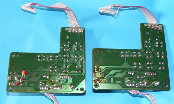
The two boards compared, modified on the left, unmodified on the
right.
The extra components on the modified board can be clearly seen, bottom
left.
On some sets (not shown here) there is also an extra chip capacitor in the top right corner near
the connector,
it's hard to remove without damaging the circuit underneath so best to leave it alone. |
|
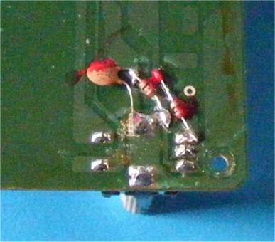
Close up of the three components that may need to be removed.
The two resistors that may need to be replaced with wire links are on
the right.
The capacitor can just be removed.
|
|
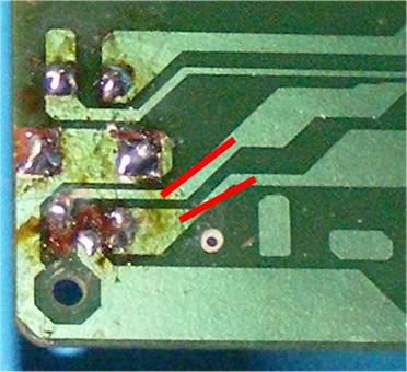
An unmodified board showing the original connections and the
approximate positions of where you may need to add two wire links to
replace the removed circuit copper tracks on modified boards.
The “mess” of flux is original and shows the poor quality of
manufacture.
Beware that the construction is awful and the metal tracks extremely
thin and fragile. They may peel away and need gluing down or replacing
with wire links. This applies to the entire radio except the Barracuda
board.
|
|
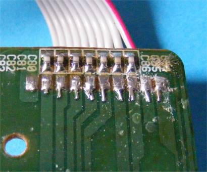
The unmodified connector end where an extra chip capacitor may have
been soldered.
Because of the size and difficulty it is probably best to leave the
extra capacitor
(which if fitted would be on the right hand end above the “C86” label)
alone.
There are extra circuit tracks under this printing which makes
removal difficult.
|
|