| YOU ARE IN: HOMEMADE 3G
EQUIPMENT |
Boost your 3G mobile
Broadband connection on a budget by making the parts yourself!
Homemade 3G Antennas -
Reflectors -
Boosters -
Software

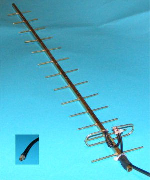
My first home brew 2.1GHz 3G Yagi aerial with the home made plug shown boxed
Construction details are lower down this page
Updated July 2010
This new page is to discuss ways to improve mobile
broadband reception for those of us who are in "not-spots" or more likely
"virtual not-spots". These are areas where the broadband signals are well
nigh useless or are perhaps more like ours - very unreliable. This site is NOT
for people who don't like getting their hands dirty with soldering, or
perhaps spending a day making something before throwing it away as a failure
only later delving into the dustbin to retrieve your design, changing a part
and then trying again. Maybe after trying the dustbin lid as a reflector on
the way! In other words it's for those of us who like experimenting.
One problem that experimenters need to make their work
worthwhile is knowing why they are doing something, so I will try to explain
in as simple terms as possible the reason why we need to do some of the
things that I am about to suggest. It's no good just saying "do this", bend
this, "do that". In this way experimenters can do what I do, learn as I go.
I have tried various ways to improve my 3G signal
levels and have reached the point where despite being on the white part of
the Three coverage map which supposedly means no coverage I can connect
reliably with two and often three bars on their signal display. In all the
cost has been a few tens of pounds at most.
If you have tried a Three Broadband dongle in the past
then I recommend that you dust it off and try again. Three have actually
done what they say in their adverts and have improved their signals in many
parts of the country. I now get 4 bars on my display using a home made
cardboard aerial, last year for most of the time I could not connect! I have
just renewed my Three Broadband contract - they gave me a 50% reduction to
keep me for 12 months more!
Let's get one thing out of the way at the start. The
dashboards from the various manufacturers like Huawei have 5 bars but these
do NOT represent signal level at all. Instead they show the amount of
corruption that is affecting your signal while it is in the ether between
their transmitters and your home. Your dongle checks the integrity of every
data packet that it receives and when there is a lot of corruption the
dongle has to keep asking for the last packet of data to be resent which
slows the whole process down. The less corruption of the signal, the less
time is wasted. It's rather like being on a phone call when you are deaf and
saying "Pardon, can you say that again please? over and over again. (I have
tinnitus so I am not disrespecting the deaf.) This can mean that to get
faster reception you sometimes do NOT need to increase your signals at all,
but instead need to reduce the interference that is getting in the way. In
this way you get your complete data faster! Much, much more on this
interesting problem later as interference is something that the home
experimenter can attack using just simple things like tin foil. Oh where
would we be without Sainsbury's or the Pound Shop?
Home
made 3G Broadband passive reflectors
Now this is something that I know a bit about as in a
previous life I worked in broadcast technology and we quite literally played
around with reflectors when designing the early satellite dishes - that's
was at Crawley Court in Hampshire, well before Sky was even a twinkle in the eye of Rupert Murdoch. I have
already designed a passive "device" that is excellent at not only boosting
received signals but just as importantly at blocking unwanted interference.
I visited a lady on the South coast recently who was too far from her
telephone exchange for a.d.s.l. broadband and she could get virtually no 3G
reception because she was also 5 miles from the nearest Three base station.
Rather importantly, and completely ignored by previous engineers who had
spend time at her home trying to help were the several dozen 70 metre high
windmills in a field not a quarter mile away off to the side of her home! As
if this wasn't enough an army firing range was behind her just down the road, this
seemed to block her signals whenever the guns were firing or the soldiers
training, which in these cash starved times was most of each day. Using my new "device" we managed to
block out much of the interference from the side and rear and get her a reliable 2 bars on Three
broadband! Ah, you will say, but there is nothing in the direct path of the signals to "get
in the way" so how can the windmills and army affect reception? You will
ask.
Well let me try to explain and see how our attempts to bring a broadband
connection to an isolated area of the South coast worked by the use of a
couple of diagrams, and I apologise in
advance for my dreadful artistic ability.

"Before" - when we started the direct data signals were often interfered
with by the reflections from the wind farm
You have to remember that mobile transmitters send out
signals in a "circle", in other words the base does not know where you are
so it sends everybody's data out in all directions. This is the reason why you
receive such a microscopic
signal as the data has to cover a lot of ground! Some of your data gets sent
direct to the house which is what you want. However a lot gets sent in the
direction of the wind farm and as this covers a much larger area than a
house even more arrives at the wind farm. The blades are very effective reflectors
of radio energy so while some of the data gets bounced straight back where
it came from a small amount bounces off the blades in the direction of the house. Now (and this is vitally important) the data
bounced off the wind farm goes a longer way round so takes a longer path (it goes round two sides of
the triangle instead of one). This data that arrives at the house from the
direction of the wind farm gets there "late", and can arrive when the dongle thinks that it
has received all the data for the moment and its oscillator has gone "out of
phase". Therefore the late arriving interference
has the effect of upsetting the good direct data already received. (This is
an obscene over simplification ;-)
This means that to make the dongle only work on the good
direct data "all" you have to do is "simply" block out as much as
possible of the interference data that comes from the direction of the wind
farm. Simple! Well no actually it isn't, as it is quite hard to block out
signals effectively (you can still listen to your car radio inside a short
tunnel for example) but my "device" takes care of all that whilst at the same time
slightly boosting
the wanted direct data. So as you will see in the next diagram the dongle now
receives the direct data with less of the interference which is absorbed so does not get in the way
of the decoding process.

"After" - the direct data makes it through while the interference is
blocked
I hope this explanation will show why even though the
wind farm was not directly in the way of the wanted signals it was still
able to exhibit a dramatic effect on signal quality.
As I said above we use Three as provider of choice. I like Three,
they have by far the better coverage of any of the mobile broadband
operators and their contention is lower - fewer people share
each channel when on line. This is probably because Three paid over £4
billion for an unused piece of the ether in which to operate. In fact they
have bought 50% more bandwidth than any of the other operators, some of which they
have still to use. Coupled with this is their price structure which if you
are prepared to sign up for a period can give as much as 15Gig of data each month for £15 - a bargain in anyone's language.
If you
look here you will see that in Horsted Keynes we
connect at a 2.5 Meg download speed - and we are outside their official service area!
The theoretical maximum speed has recently risen to 7.2 Meg along with the other 3G operators, although
this increase is very dependant on signal strength. We have one of the
latest "up to 7.2 Meg" dongles, it is dreadfully insensitive! We'd rather
have a good 2 meg connection than an unreliable 5 Meg connection any day!
When deciding how much information to write on this page
I had to choose whether to explain why the delayed data was bad for
the dongle or just state it as a fact without explanation. It's all to do
with oscillator phases and my explanation above is truly dreadful; whilst I
could go into full details I have decided to put just enough information
to enable you know why you are doing something rather than giving a
lecture on electronics theory. I hope the above diagrams do that without
being too boring.
So you now hopefully understand that you need to remove
interference, some of which may not even be in the direct path, whilst still
letting the wanted data through and knowing that we can get down to
designing a device to do
this.
3G and Wi-Fi reception consultancy
service
I hope to be able to publish plans for making my
"device" very soon after I have received some legal advice about
whether they are patentable. If you need help
with a similar connection problem or just want a rough idea of how my "device" works do
please get in touch. Whilst I do not offer a consultancy service as such
(having retired) I am always interested to see what help I can offer those
who have unusual reception or networking problems so don't hesitate to send
me an email. I can be contacted at 3g @ the domain that you are connected to
dot com. There is also a link to a different address that is forwarded to me
at the foot of every page on this site. Sometimes messages (particularly for some reason messages from aol
) get trapped as spam. If you don't get a reply within a few days please try
again.
By the way like the rest of this page low cost, or
shall we say "Recession Prices, are essential and it would only cost
you a few GBP to make a copy from parts available in almost any small
town.
Some of the other subjects to be covered on this page
will be...
Home made 3G aerials

The working end of an experimental 2GHz Yagi
made of 2mm brass rod, cable ties and glue!
Connecting from a static location is rather different
to using your dongle when out and about. When in a fixed position it is
possible to use a directional Yagi type of antenna array - that's a small TV aerial to you
and me. This design was invented by a Dr. Yagi in Tokyo in 1926 and now used on almost
every rooftop in the world. The good thing is that 3G broadband uses much
higher frequencies than TV so the aerial is correspondingly much smaller
(frequency α wavelength), in fact a good one can be less than a foot long. You can see
a couple of pictures of my prototypes on this page. To make one similar you
need smaller parts than for a telly aerial and a model shop should have all
the necessary metal (except the plug, which you can also make, see below)
for under a tenner. Not bad when 3G Yagis are sold for up to £200 on some
web sites! (The manufacturers sometimes hide them in a plastic pipe to make
their device look more modern, but inside it's just bent metal!)
I have now made several Yagi style aerials for 3G
using modelling brass strip and most work well, but to be honest none as
well as I would hope, so it's still a work in progress. The lack of signal
strength may be down to my accuracy. The director strips need to be cut and
placed to an accuracy of 1mm or less. Such accuracy comes hard to a
spectacle wearer, but I'm working on it and hope to improve signals a lot
before publishing my design. However I have read reports that some of these
expensive units sold on eBay don't work that well either. I have recently built a simple
flexible whip (a bent cloths hanger) and this works surprisingly well, with
the advantage that a whip aerial can be left outside when it rains.
Further down I will describe a simple Yagi but must
point out that the design may well be modified in the light of experience.
The "bent hanger" whip will be the next item on the page.
|
"Cheap
'n cheerful" CRC9 Huawei 3G dongle aerial plug
More drawings are in preparation - please look back
in a day or two
|

A couple of my early prototype plugs without cable
|

An adapter to fit an Huawei dongle to a standard aerial
|
First I will give you my simple cheap design for a
plug to fit the aerial socket on Huawei 3G dongles. You can use these
plugs to connect your experimental aerials. I haven't seen this size of
plug called CRC9 for sale at less than £5. My design, which I have now
repeated many times costs perhaps 20p in parts. May not be as beautiful
to look at but who cares - it works and if you drop it on the floor just
make another!
To make a plug the size of a CRC9 to fit the
Huawei socket you will need, a small piece of thin brass from a model
shop, a 2mm drill (can be blunt!), a piece of tube from a can of WD40 or
similar - 2mm tube is often used for squirt aerosol products, some
Araldite - preferably rapid cure, soldering equipment, and a small piece
of brass wire or failing that use some fuse type wire or perhaps even in
an emergency an unbent paper clip.
Cut a piece of brass to 6 or 7mm x 10mm. Roll this
round the blunt end of the 2mm drill as this will be slightly over size
and you actually need 2.2mm internal diameter to fit the socket. When
you make the cylinder it is helpful if there is a small gap left (in
other words not quite a complete circle) as this will make it easier to
"spring" and fit tightly. You could of course always wrap a piece
of paper round the drill former first to make its diameter slightly
larger. To the end of the newly made cylinder tin a small part for
easier soldering the wire screen later without overheating and melting
the plastic. Cut off two "ears" from the corners of the end of the brass
away from the dongle to make a place where you can bend the centre wire
over without shorting out. Look at the diagrams and photos, they are
much clearer and to be honest you could do the job just by looking at
them without bothering to read these words at all!
Next cut the tube about a couple of mm long, this
is your insulator/spacer. Push a few mm of the wire through the spacer
and bend over the end. Chose a size of wire that is a firm fit in your
dongle socket, not too lose nor too fat. I used a piece of wire from a
capacitor, you might use some old fuse wire or brass wire if you can
find it. Fix this wire in place with a tiny blob of Araldite at the
"top" end away from where it will go into your dongle as you naturally
don't want to put Araldite in your dongle! After this has dried
push the spacer with its wire attached through to line up with the back
end lining up the wire bend with the two "ears" to avoid a short
circuit. Fix in place again with another small blob of Araldite. It's
worth making i[p several of these plugs at one time as it is impossible
to make a small enough blob of Araldite and anyway the parts will be to
hand. You can always use the best ones and junk the rest.
After this solder on your co-ax connecting cable
screen to the previously tinned brass strip, centre to centre, and then
cover the end up with a blob of Araldite shaped when almost dry to make
a handle to push and pull when inserting. Set this entire unit aside to
dry properly.
Here is a tip. You should really ensure that the
wire is central while the Araldite dries - overnight is best - and it
might fall to one side while drying. I usually risk it and leave the
plug just slightly in the dongle socket while it dries. If you are going
to make several of these plugs then you might prefer to make up a small
fake socket or perhaps just use another piece of WD40 tube (unglued) to
hold it all in alignment. A little grease will stop the tube sticking
while the Araldite dries.
Finally cut the wire so that it protrudes about
4mm or so out of the end of the brass screen and there you are! A cheap
'n cheerful plug to attach your experimental aerials to your Huawei
dongle!
|

The brass is cut to roughly this shape |

My attempt at a diagram of the plug design
|
|
|
A homemade
2.1GHz Yagi antenna for 3G broadband
Now it's time to look at how you might make a Yagi
aerial (antenna) to improve your 3G mobile broadband reception. The
advantage of using a Yagi type of aerial is that first it is directional. By
its very design it will reject signals coming from the side - in this design
it will only accept signals coming at an acceptance angle of 35degrees. That means
that signals from the side at 90 degrees, or to a lesser degree from the back at 180 degrees will be
at a much lower level than those from the front.
This is a neat way to help with the problem described
above when there is a source of interference at the side or back. So why try
my "device" and why not use a Yagi for every purpose? The answer is the
connecting lead. You see it attenuates or reduces the signals - a lot! If an aerial gives a gain
of say 12dB (that's a lot in this design) then after going down a 10 metre lead of normal
quality you will actually end up with less signal at the plug than using a small whip aerial
with a one metre lead!
If this were a TV reception problem then we might
consider a device called a pre-amp. This sits right on the back of the
aerial and amplifies the signals before they go down the lead. That wouldn't
work on 3G broadband as we need to send signals in both directions, both up
and down. A suitable two-way device could be designed but it would be both
difficult and expensive to build ourselves! Anyway, we will describe here
the design of a Yagi and leave it to you to put it on the shortest low loss lead
possible.
The quarter inch (6mm) square metal strips that we
will use for the centre spine of our aerial are sold by model shops in 30cm
lengths so we will design an aerial to fit on such a back bone after
allowing an inch or two on the rear end for a mounting bracket. To build this
antenna you will therefore need a single length of 6mm square box section
brass and three lengths of 2mm solid brass rod, also some solder, plumbers
solder is best, some flux and a hot soldering iron or a blowtorch. If
you don't have a blowtorch available then you can stick most of it together
with Araldite and leave the soldering just for the cable connection to the
active element. Total price for the metalwork is about £5 or £6. on top
of this you will need some suitable co-ax lead (details of how to obtain
this cheaply later on) and one of my famous home made plugs! Total cost for
the whole thing, less than £10!
Again I will stress that you should connect this
aerial to your dongle by the shortest lead made of the highest
quality cable. Use anything over 8 or 10 metres and you'll end up with less
signal than you started with! So if you have plans to put this aerial on
your chimney consider putting your dongle under the slates on a long
amplified USB extension. In the past it wasn't possible to run USB devices
more than a couple of metres from your computer. Now that amplified
extensions are available this can be increased to 10 metres by putting two 5
metre leads in series. The manufactures of the extensions claim that you can
daisy chain up to 5 leads together to get 25 metres away. In our experience
no computer can supply sufficient current through its USB socket to run so
many amplifiers plus a dongle. You could try a powered USB hub but we still
doubt that 5 leads in line would work.
If you absolutely have to get this far away from your
computer then use a device called an Ethernet USB extension. This uses two
special adapters at each end and a normal network lead in the middle - up to
60 metres may work. The one drawback (apart from cost) is that with a high
current device such as a 3G dongle you absolutely have to have mains power
at the far end of the connection. Hardly convenient on your roof in a a rain
storm!
WORK IN PROGRESS - MORE SOON
|
3G
Boosters
These are electronic devices that, believe it or
not(!), amplify or boost the signals down from the mobile base station and
then boost your data before it is sent back up. It's quite difficult to make
a suitable unit from scratch, but much easier to modify existing devices
such as those made for Wi-Fi to work at the adjacent 3G frequencies. We have
tried modifying an amplifier sold for wireless internet frequencies to
the 2GHz frequencies used by 3G. This does work after a fashion but we are
faced with the problems mentioned above of increasing the interference just
as much as the wanted signals. It is perhaps for this reason that there
seems to be a dearth of professionally made 3G boosters in this country. In
the wide open spaces of the USA and Australia though it is a different
story!
You can make a start and can easily get a femtocell
amplifier for many mobile phone providers but that is not really what we are
looking for on this web site. We are looking for a long term reliable
broadband signal rather than occasional short term phone calls. We are
working on the problem...
Home
brew 3G software to make the best use of what signals you can get
for example by combining two connections into one. When one goes down the
other may well get better! I have one example running at present although
it's not yet good enough to publish.
LOTS and lots more to come including some hard
details, plans and hopefully some details of when you can get suitable parts
cheaply. Please look back in a few days. Always pleased to hear from you.
Rob.
|